RCFS
Radio Control Fail-Safe
RCFS
is a tiny microcontroller based device that adds Fail-Safe features
to any PPM (AM/FM) radio control system. It is very simple to build
-- only three components!
Expensive
PCM based R/C receivers have the ability to detect radio reception
problems. On these systems, if the signal integrity is poor, the
servos' positions can be programmed to default to emergency
conditions.
However,
Fail-Safe is not a common feature on the lower cost PPM systems. The
Multiplex IPD
Receiver family offers it, but none of the other radio makers
have bothered to add it to any of their standard R/C systems.
However, with the RCFS device discussed here, you can add Fail-Safe
to ANY servo that is used on a standard PPM (AM or FM)
radio control system. Cost is less than $3 per channel.
What Goes Up Must
Come Down
The intent
of any Fail-Safe system is to help reduce the danger that might
occur when a model aircraft loses radio contact. Regardless of how
you may personally feel about PCM radios and their Fail-Safe mode, I
believe that most folks agree that programming an out-of-control
model to slow down is not a bad idea.
The model
will still crash, but hopefully the reduced speed will give it, as
well as the folks on the ground, a better chance to survive the
mayhem. It probably does not hurt to help stabilize the uncontrolled
servos too, something that a Fail-Safe will also do for you.
Unlike the
more sophisticated PCM systems, the RCFS can NOT be used to help
clean up a "noisy" R/C installation. If your model is plagued with
erratic servo glitches then do not expect this device to tame your
problems. Yes, a PCM system would help, but blindly fixing the
glitches with PCM is often considered a mistake by most experienced
R/C'ers. That sort of discussion has already filled megabytes of
space on the popular R/C forums, so I will not comment any further.
The bottom line is that the RCFS will not help you in this
area.
The
Fail-Safe behavior on RCFS differs from what you would experience on
a typical PCM system. We will talk about that in a moment. But for
now, let me say that the RCFS attempts to address some common
complaints. Most importantly, I wish to make it clear that using the
RCFS device, or any other Fail-Safe system, is at YOUR risk.
Control
Freak
RCFS is
installed between the R/C receiver and servo. It constantly analyzes
the incoming servo pulses and looks for serious trouble. Using a
microcontroller, the pulses are checked to see if they fit within a
allowable range, in a template sort of fashion. If the pulses
are found to be acceptable, they are merely passed along to the
servo. You will have full control of the model and RCFS remains a
passive passenger at this point.
If the
pulses are missing (lost signal) or invalid (noisy signal) then the
RCFS attempts to determine the extent of the trouble. If the problem
persists for more than a second the Fail-Safe feature is enabled.
During Fail-Safe, RCFS takes control of the servo position. It can
be set to hold the last valid position or it can move
the servo to a preset position.
Complaint
Department
My approach
attempts to minimize the Fail-Safe's intervention. One of the common
complaints with PCM Fail-Safe is that it totally masks reception
troubles, especially the brief intermittent type. On a PPM system,
these sort of "glitches" can be felt, so detecting trouble
before things get out of hand is easier to recognize. I too
believe that it is an advantage to be able briefly witness most
glitches.
It is for
this reason that the RCFS has been designed to NOT mask any brief
periods of radio "hits." Random radio hits will be felt during the
short windowing period. If the servo signal consists of a collection
of good and bad pulses, the RCFS will do its best to remain off in
order to allow you to "fly through" the noise. For sure, totally
loss of radio contact will cause the Fail-Safe to switch on after
the brief delay.
Note:
Noisy signals that contain substantial amounts of valid servo pulses
will not activate the Fail-Safe mode. This can be a blessing or a
burden, depending on the situation. As I mentioned, this is so that
your stick commands have a chance of getting through. A PCM system
would either (1) mask the corrupted signals or (2) switch to
Fail-Safe in extreme situations.
Timing is
Everything
 The servo signal is
a simple digital pulse. It spends most of its time at a logic low
(0V). About every 20mS it goes logic high (4-6VDC) and then quickly
goes low again. It is this tiny window of logic high time, called
the pulse width, that gets the attention of the servo. The servo signal is
a simple digital pulse. It spends most of its time at a logic low
(0V). About every 20mS it goes logic high (4-6VDC) and then quickly
goes low again. It is this tiny window of logic high time, called
the pulse width, that gets the attention of the servo.
Please
refer to the drawing. The period labeled "A" is called the frame
rate. In the example it is repeated every 20mS (50 times per
second), which is quite typical for many radio systems.
Modern
servos define center as a 1.5mS pulse width, as shown by detail "B"
in the drawing. Full servo rotation to one side would require
that this pulse width be reduced to 1.0mS. Full rotation to the
other side would require the pulse width to increase to 2.0mS.
In the eyes
of RCFS, good servo pulses will be between 0.75mS and 2.25mS long.
Even though a normal servo signal is 1.0mS to 2.0mS, some
transmitters offer ATV settings that can extend the timing beyond
that. The wider range taken by RCFS allows compatibility with such
radio systems.
When servo
pulses do not fall within the allowed range, they are flagged as
"corrupt." When corrupt pulses are encountered, they are monitored
for a one second period to ensure that there is sufficient cause to
switch to Fail-Safe. The threshold before switching to Fail-Safe is
managed by a complex software algorithm that was developed
specifically for this project.
Lost and
Found
Besides the
Fail-Safe feature, you can also upgrade RCFS to include a Lost
Model Finder feature. All it takes is a transistor and a loud
Sonalert type piezo transducer. If you do not need the Fail-Safe
support then a single IC circuit is all that is needed to make a
complete Lost Model Finder. The schematic shows the details.
With the
Lost Model Finder option you will be able to locate your downed
aircraft simply by turning off the R/C transmitter. Just listen for
the screaming beep tone. You may not be able to see it, but you will
now be able to hear where the model is hiding.
Less is
Best
The parts
count in this project is minimal. All it takes is an 8-pin PIC
microcontroller, 14-pin CMOS Nand Gate IC, 3-position DIP switch,
and a capacitor. Shopping for these parts will be a breeze, since
they are all available at Digi-Key. Your wallet will be
happy too, since material cost is very low.
The chosen
microcontroller is from the vast offerings of Microchip Technology. Actually,
your exact PIC choices have some flexibility. You can use a
PIC12C508, PIC12C508A, PIC12C509, or PIC12C509A.
The
PIC12C50x is not a "Flash" part, so you will need a traditional PIC
chip programmer to "burn" the hex file's object code into the
microcontroller. Be sure to select the configuration fuses during
chip burning as follows (these are optional settings within your
chip programmer's menus):
|
WDT: |
Disabled |
|
MCLR: |
Disabled |
|
Oscillator: |
IntRC |
|
Memory: |
Protected |
The CD4011 Nand
Gate is used as a 2:1 signal Mux. The PIC's SIG_OK control line
determines the Mux's signal source (R/C receiver or PIC Fail-Safe).
Please note that Pin 14 connects to +V and Pin 7 is ground.
The DIP
switch is used to enabled the Fail-Safe preset positions. It is
actually three little SPST slide (or rocker) switches in a
single package. You could also use a header with shorting blocks, or
simply use jumper wires if you do not need to change the settings.
The switch settings are as follows (ON = CLOSED, OFF = OPEN):
| SETTING |
POS2 |
POS1 |
POS0 |
Fail-Safe MODE |
PULSE WIDTH |
|
0 |
ON |
ON |
ON |
Fail-Safe HOLD |
-- |
|
1 |
ON |
ON |
OFF |
Preset Mode, -60º |
1.0mS |
|
2 |
ON |
OFF |
ON |
Preset Mode, -40º |
1.2mS |
|
3 |
ON |
OFF |
OFF |
Preset Mode, -20º |
1.3mS |
|
4 |
OFF |
ON |
ON |
Preset Mode, 0º (Center) |
1.5mS |
|
5 |
OFF |
ON |
OFF |
Preset Mode, +20º |
1.7mS |
|
6 |
OFF |
OFF |
ON |
Preset Mode, +40º |
1.8mS |
|
7 |
OFF |
OFF |
OFF |
Preset Mode, +60º |
2.0mS |
RCFS
Construction:
Even though
it is very simple, this project is best tackled by an experienced
electronic technician. If you have successfully built any of the
other RC-CAM Electronics Projects
then you should have no problem with this one. Entry level
technicians should plan on getting some hands-on help.
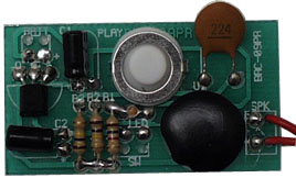
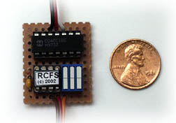
The RCFS
board can be built using nearly any technique you wish. It really
deserves a printed circuit board, but mine was built on a tiny piece
of phenolic perf board. Be sure that your construction technique is
worthy of a model aircraft's environment.
Layout is
not critical.  The circuit was point-to-point
wired using 30 gauge insulated Kynar wire. This wire is normally
used for wirewrapping, but works fine with a soldering iron. I
recommend a temperature controlled iron (700° tip). The circuit was point-to-point
wired using 30 gauge insulated Kynar wire. This wire is normally
used for wirewrapping, but works fine with a soldering iron. I
recommend a temperature controlled iron (700° tip).
The circuit
can be hardwired to a servo's cable. However, I used a six inch
servo extension that was cut in half. Installation in the model
plane is a plug-and-go sort of effort.
Check it
Out
Simple
mistakes can destroy electronic parts and may generally ruin your
day, so check your work carefully. Do not install the receiver
battery until you have verified that the power leads are not shorted
(use an ohmmeter). If all looks good, plug the RCFS into a channel
of your PPM receiver.
Do NOT
install the PIC chip until you have verified that U2 pin 8 is ground
and the pin 1 has 4.5 to 6.0 VDC on it when a battery is connected.
Remove the battery BEFORE you install the chip.
Now it's
time to test your work. Just follow these simple test steps:
- Turn on
your transmitter and verify that the stick controls the servo.
- Turn off
the transmitter. In approximately one second, the servo should
"Fail-Safe."
- Turn on
the transmitter and verify control is regained within a
half-second.
- Repeat
the test for all eight combinations of the DIP switch
settings.
Design
Documents:
The
technical details are available as file downloads. There is no
charge for the information when used in a personal (hobby) project.
Commercial users must obtain written approval before use.
Please be
aware that the information is copyright protected, so you are not
authorized to republish it, distribute it, or sell it, in any form.
If you wish to share it, please do so only by providing a link to
the RC-CAM site. You are granted permission to post links to the web
site's main page (http://www.rc-cam.com/). Please
respect this simple request.
 |
Schematic Files: PDF file of the RCFS circuitry.
All major components are from http://www.digikey.com/.
Revision: Rev A, dated 06-17-2002 |
|
PIC Object Code: Hex file of the compiled RCFS
firmware. You should occasionally check for updates.
Revision: V1.0, dated
06-17-2002. |
The Small
Print:
| If
you need a part then please consult the sources shown in the
project (see schematics download). I do not work for, nor
represent, ANY supplier of the parts used in RCFS. Any
reference to a vendor is for your convenience and I do not
endorse or profit from any purchase that you make. You are
free to use any parts source that you
wish. |
All
information is provided as-is. I do not offer any warranty on its
suitability. That means that if you build and use this device, you
will do so at your own risk. If you find documentation or software
errors then please report them to me. |